Osco Gate Operator Wiring Diagram

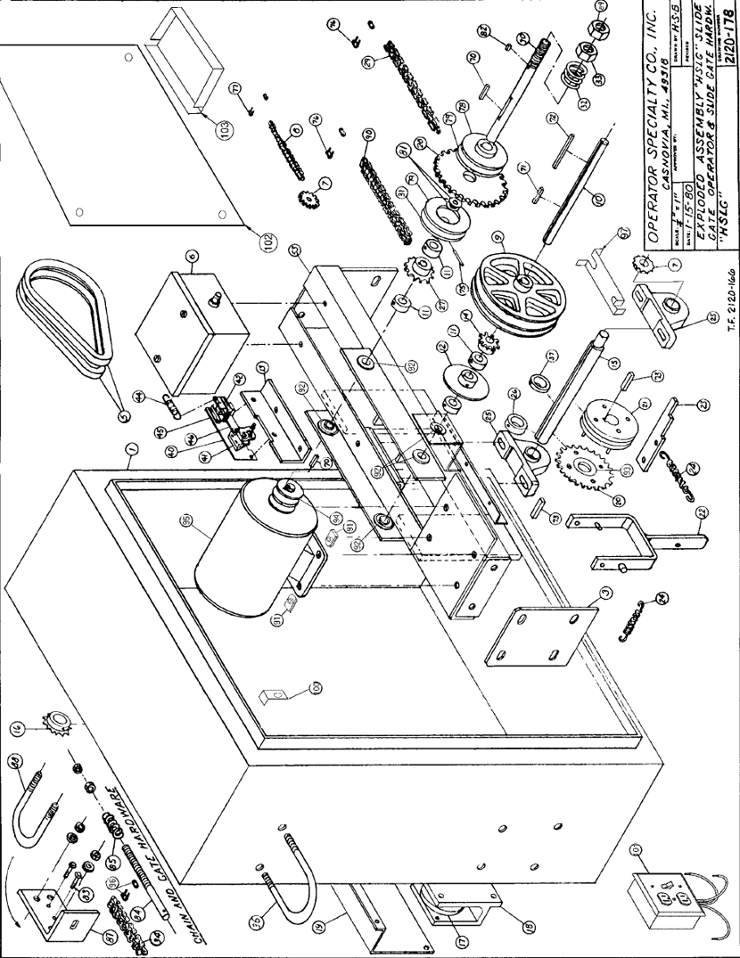
Osco Hslg Gate Opener Sliding Commercial Operator Manual Manualzz

Eo 4894 Osco Door Opener Wiring Diagram Schematic Wiring

Osco Swc Swd Swr Swing Gate Openers Manual Manualzz

Osco Gslga Slide Gate Operator

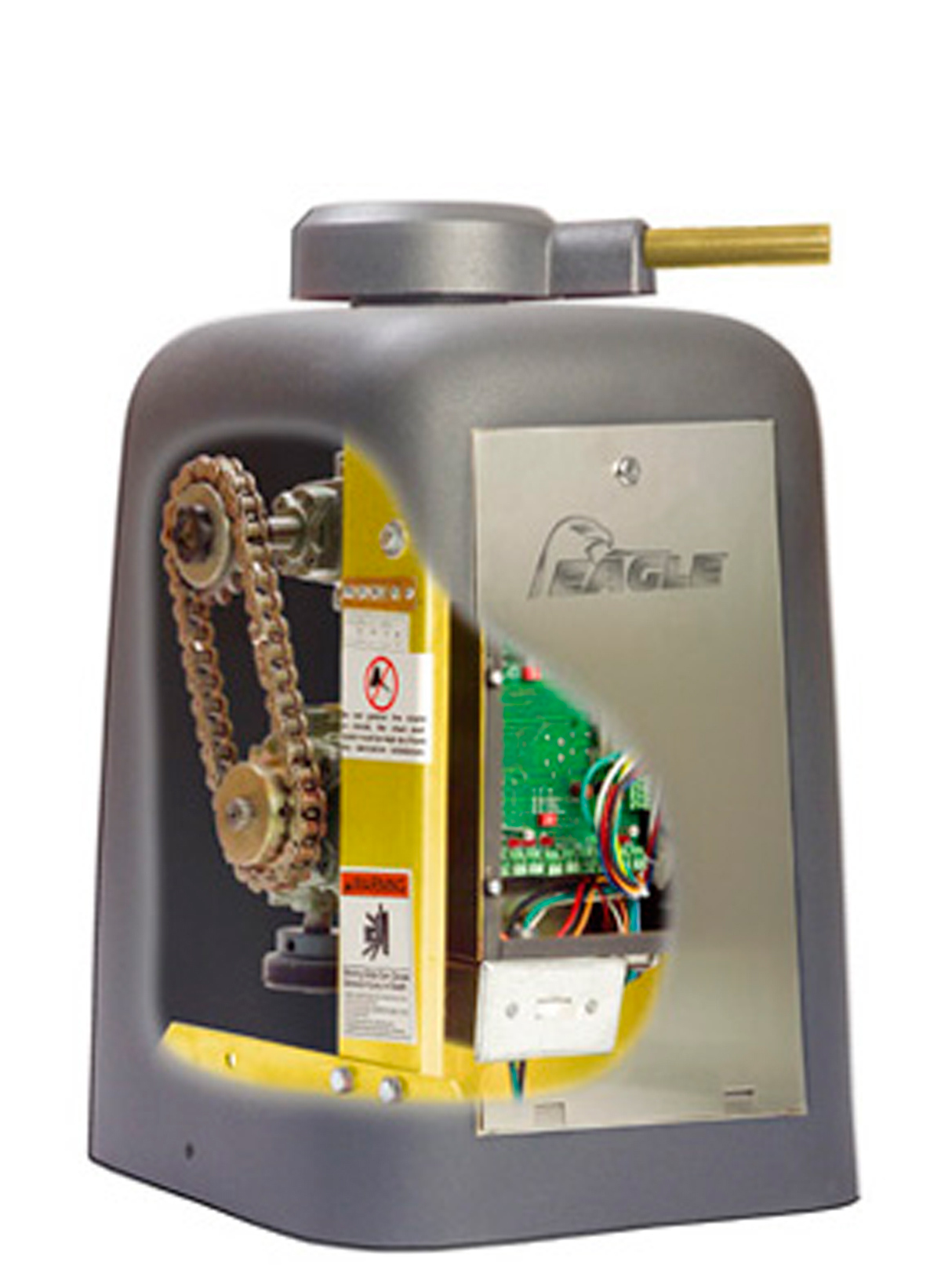
Osco Hslg Slide Gate
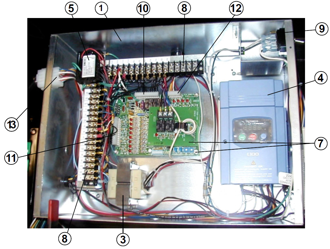
Osco Gate Opener Repair Parts Osco Swing Vs Gswg Parts Control Panel
Collection of osco gate operator wiring diagram.
Osco gate operator wiring diagram.

Linear Swg 111 1 Hp 115 Volt Single Swing Gate Operator Linear Pro Access Linear Gate Operators

Wiring Diagram 6002 Manualzz

Gatemotors Net Osco Linear 1 2 Hp Commercial Slide Gate Operator Commercial Slide Gate Operators
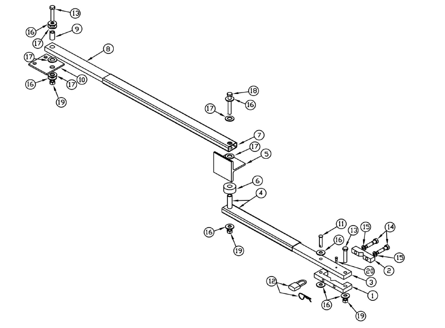
Repair Parts Osco Gate Operators Swd Osco Arm Assembly Repair Parts

Linear Osco Slc 111 1 Hp 115 Volt Commercial Slide Gate Operator Linear Pro Access Linear Gate Operators

Osco Swg Swing Gate Operator
Osco Sliding Gate Opener Replacement Parts Osco Hslg Gate Opener Parts

Linear Osco Slc 121 1 Hp 230 Volt Commercial Slide Gate Operator Linear Pro Access Linear Gate Operators

Linear Swd 211 Swing Gate Operator With Battery Backup Linear Pro Access Linear Gate Operators
Automatic Gate Openers Osco Crs Medium Duty Swing Gate Operator

Linear Gate Operators

Linear Osco Slc 211 1 2 Hp 115 Volt Commercial Slide Gate Operator Linear Pro Access Linear Gate Operators

Linear Nortek Swr 211 Swing Gate Opener 1 2 Hp For Gates Up To 17 500 Lbs

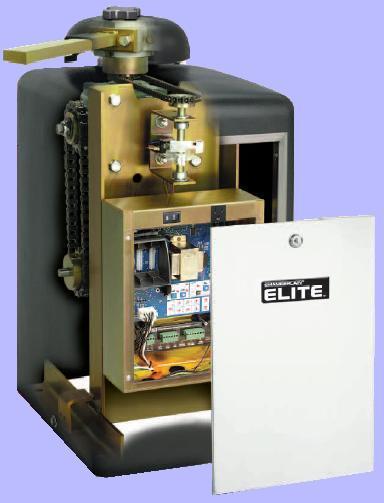
Elite Sl3000ul Elite Q028 Manual Crank

Swr Osco Residential Automatic Gate Operator From Operators Specialities

Power Master Rsg Residential Sliding Gate Opener Powermaster Opener
Osco Slide Openers Osco Sliding Gate Openers Osco Slide Gate Openers

Gate Opener Automatic Sliding Gate Openers
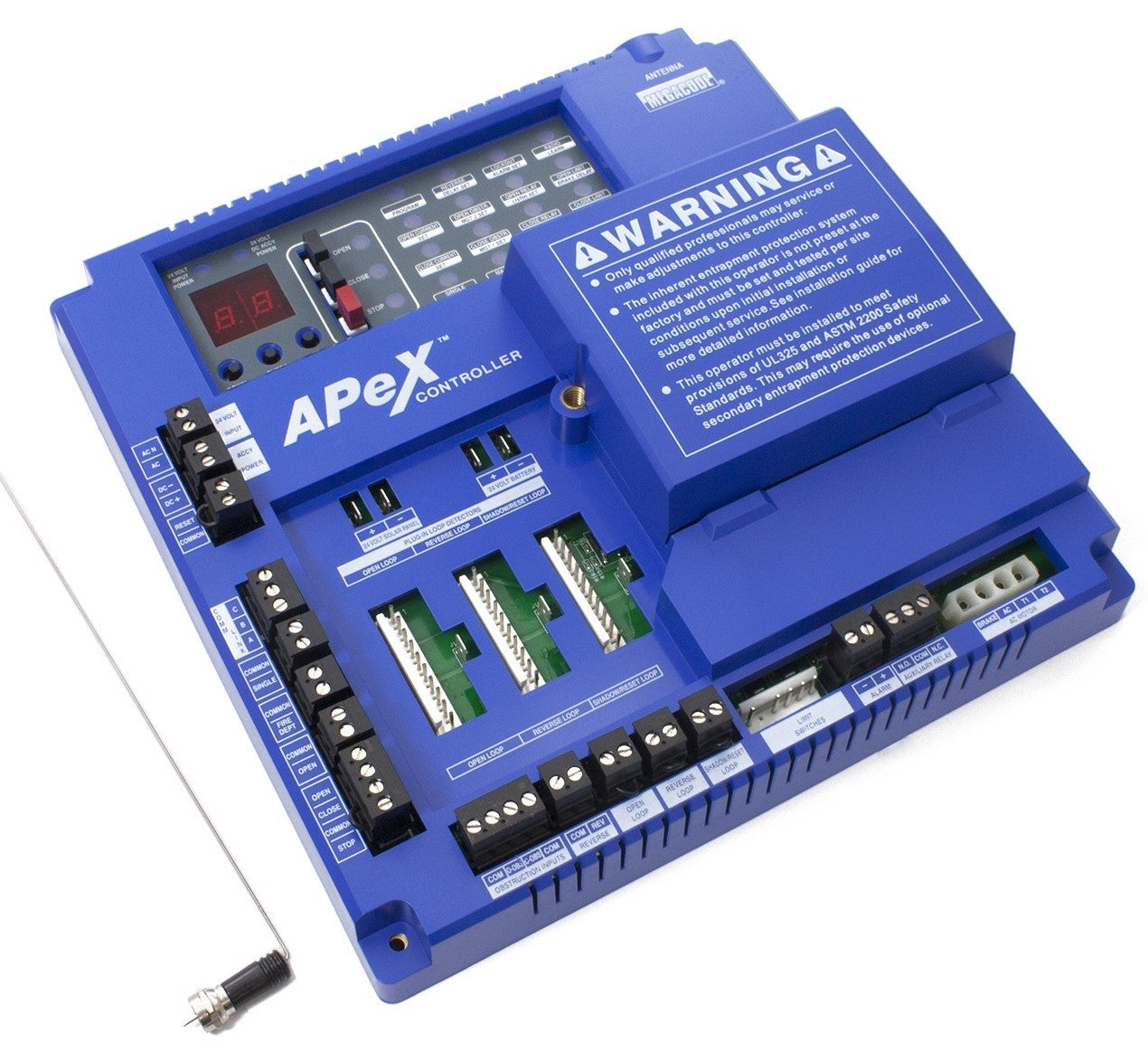
02 Linear Osco 2500 2393 Apex Control Board Protec Controls
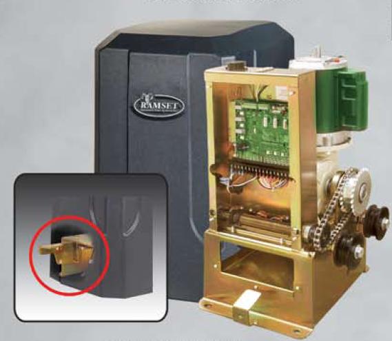
Ramset Gate Opener Ramset 1000 Sliding Gate Opener Ramset Slide Gate

Linear Osco Apex 2500 2393 Sld Control Board Module
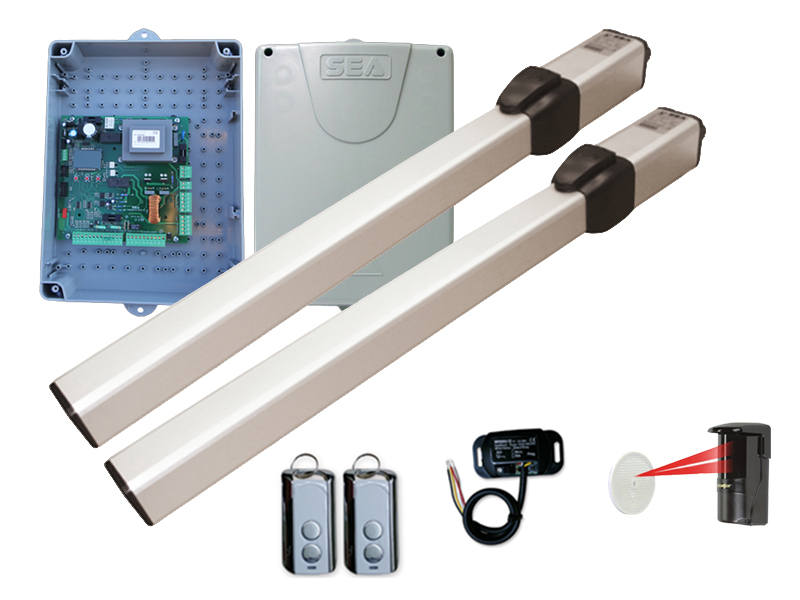
Sea Mini Tank Hydraulic Swing Operator Residential Swing Gate Openers
Elite Gate Openers Elite Swing Gate Operators Elite Remote Gate Opener

Linear Osco Sld 211 Slide Gate Operator
Source : pinterest.com
